Introduction to Blender
Instructor-Led
We will follow a lecture format with live demonstrations. I strongly encourage you to participate actively by replicating each demo as it is presented. This hands-on approach, akin to experiential learning, enriches your learning experience and empowers you with practical skills through direct engagement.
Because we need to cover a substantial array of concepts within our three-hour timeframe, reviewing the notes thoroughly before the next hands-on session is highly advisable. This review will strengthen your grasp of the material and better prepare you for active participation in the upcoming session.
Feel free to ask questions at the end of each section. If you need clarification or further information on any topic discussed, don’t hesitate to speak up.
Hardware Requirements
Blender Foundation recommendations
Blender does have some special hardware requirements that may not be satisfied by the average computer. Blender.org lists the minimum hardware requirements as follows:
- 64-bit quad core CPU with SSE2 support.
- 8 GB RAM.
- Full HD display.
- Mouse, trackpad or pen+tablet.
- Graphics card with 2 GB RAM, OpenGL 4.3.
- Less than 10 year old.
Please note that these are the minimum system requirements. If you are planning on using this software to create more advanced projects, it is best to look at what Blender artists recommend.
Additional Notes:
Graphics
It is best to have a Dedicated Graphics Card for using 3D software like Blender. 3D modeling and rendering typically utilizes large amounts of virtual memory. Dedicated graphics cards have additional virtual memory for this purpose. Some integrated graphics systems in laptops and mini computers work for light projects as well. It is best to do a bit of personal research into the matter.
Most cards over the past decade will be just fine so long as you're packing at least 2GB of video memory on the Nvidia GeForce 400 series, AMD's Radeon HD 7000 range, or newer. CPU-wise, you're looking at a quad-core processor to get the program running.
If this information is making your head spin, then the demo scene stress test should at least confirm that your computer will work for this course.
Mouse
I urge you to use a dedicated mouse with a mechanical clickable centrewheel. The clickable centrewheel will be used often for panning and rotation of the 3D scene. Most mid-grade dedicated mice include this feature.
Until you are familiar with the interface, please do note use:
- A trackpad
- A touch-based mouse eg. Apple Magic Mouse
- A digitizer tablet eg. Wacom
If you in need of a different mouse, here are a few low cost recommendations that are easy to find online or pick up at staples. Note: both of these mice do not have bluetooth and require a USB A port for the wireless receiver.
Microsoft 2.5 ghz wireless 1850 mouse on Amazon Canada
Logitech 2.5 ghz wireless M325 mouse on Amazon Canada
Display
Blender has a rather large and complex user interface with many small buttons and windows. It is best to use a large, high resolution monitor in order to maximize the UI spread. Otherwise, buttons may be hidden or minimized, causing some confusion for the uninitiated.
Install & Test
A) Overview
Downloading and installing Blender is normally a straightforward process. However, if you have never tested the software on your particular computer hardware it is best to download, install and open a demo file for quick testing. Furthermore, I would like to ensure we are all using a similar installation with default settings and layout.
B) Recommended Blender version
Blender is under constant development meaning there are small incremental releases happening weekly. Implementing small changes on a constant basis can cause instability or bugs to the end user. I recommend downloading a Long Term Release version as these versions are intended for studios that favor reliability over new features. The latest (LTS) release version is version 4.2
Direct Link to 4.2 LTS release download
C) Running a demo file
Once you have Blender installed, it is best to open a demo scene to check for crashing or other bugs. There is a page hosted by the organization that allows anyone to download open sourced demo scenes.
1. Download demo scene
This course will not be taxing on your system as we are using basic features. I recommend downloading the 'Classroom Scene' created by Christophe Seux. Here is a direct link to downloading the file.
2. Open demo scene
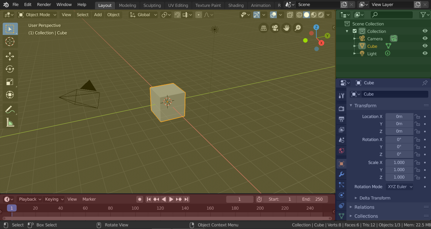
Once you have downloaded the demo file, unzip it and open the classroom.blend file. Upon first opening the file you should see this:

3. Enable 'Viewport Shading'
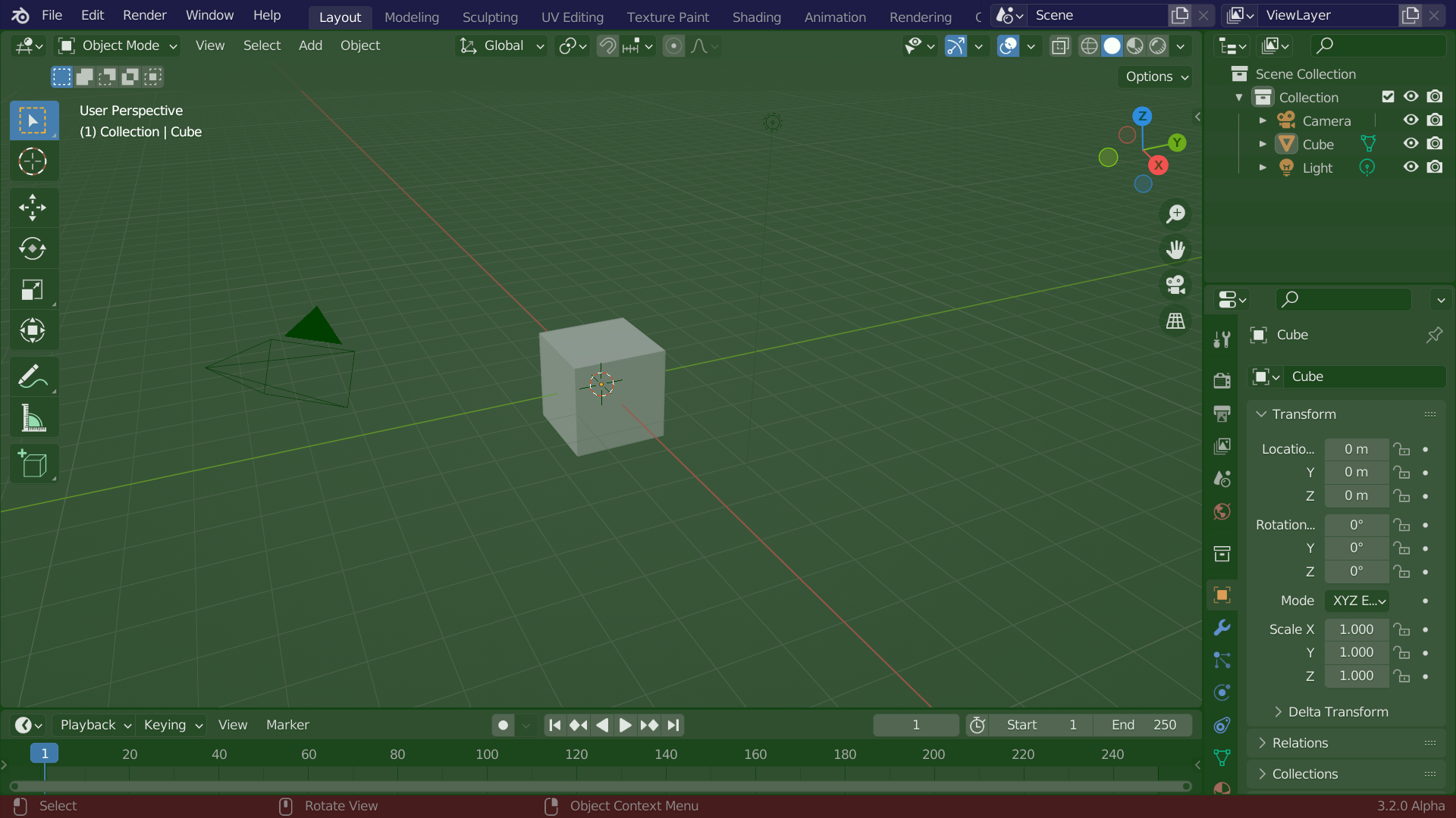
In order to test the capability of your computer for rendering click this button circled in red:

Once you have clicked the 'Viewport shading button' as indicated by the red circle, patiently wait for the scene to load. The time to load varies depending on what computer you are using. I would suggest leaving this process for 1-10 mins.
4. Confirm the demo scene has rendered correctly
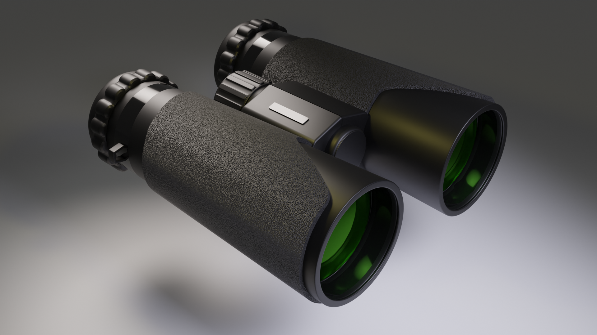
The scene should render within that suggested timeframe and look like this. Note: there is text in the upper left corner that indicates the loading, rendering and completion of the scene as indicated here.

If your scene looks like this screenshot then you have successfully stress tested your machine and are ready to take on this course. By completing this stress test we can now deduce that:
- Your Blender 3.3.3 installation was successful.
- You have opened your first Blender file.
- Your machine is capable of rendering [Raytraced.](https://en.wikipedia.org/wiki/Ray_tracing_(graphics)"Wikipedia Page for Raytracing Graphics") light successfully.
- You are ready to begin the course!
Basic Shortcuts
A short list of heavily used keyboard shortcuts baked into Blender by default.
Object Mode Shortcuts
Mac Shortcuts
| Description | Shortcut |
|---|---|
| Select All | Command (⌘) + A |
| Multi Select | Shift + LMB |
| Cut | Command (⌘) + X |
| Copy | Command (⌘) + C |
| Paste | Command (⌘) + S |
| Copy + Properties | Command (⌘) + Alt + C |
| Paste + Properties | Command (⌘) + Alt + V |
| Delete | X |
| Sidebar Collapse/Show | N |
| Contextual Pie Menu | ~ |
| Object/Edit Mode Toggle | Tab |
| Grab | G |
| Free Move Along X Axis | G + X |
| Free Move Along Y Axis | G + Y |
| Free Move Along Z Axis | G + Z |
| Rotate | R |
| Rotate Around X Axis | R + X |
| Rotate Around Y Axis | R + Y |
| Rotate Around Z Axis | R + Z |
| Hide | H |
| Isolate Selection | Shift + H |
| Unhide All | Alt + H |
| Confirm Operation | Return |
| Cancel Operation | Esc |
| Add Item to Scene | Shift + A |
Windows Shortcuts
| Description | Shortcut |
|---|---|
| Select All | Ctrl + A |
| Multi Select | Shift + LMB |
| Cut | Ctrl + X |
| Copy | Ctrl + C |
| Paste | Ctrl + S |
| Copy + Properties | Ctrl + Alt + C |
| Paste + Properties | Ctrl + Alt + V |
| Delete | X |
| Sidebar Collapse/Show | N |
| Contextual Pie Menu | ~ |
| Object/Edit Mode Toggle | Tab |
| Grab | G |
| Free Move Along X Axis | G + X |
| Free Move Along Y Axis | G + Y |
| Free Move Along Z Axis | G + Z |
| Rotate | R |
| Rotate Around X Axis | R + X |
| Rotate Around Y Axis | R + Y |
| Rotate Around Z Axis | R + Z |
| Hide | H |
| Isolate Selection | Shift + H |
| Unhide All | Alt + H |
| Confirm Operation | Enter |
| Cancel Operation | Esc |
| Add Item to Scene | Shift + A |
Linux Shortcuts
| Description | Shortcut |
|---|---|
| Select All | Ctrl + A |
| Multi Select | Shift + LMB |
| Cut | Ctrl + X |
| Copy | Ctrl + C |
| Paste | Ctrl + S |
| Copy + Properties | Ctrl + Alt + C |
| Paste + Properties | Ctrl + Alt + V |
| Delete | X |
| Sidebar Collapse/Show | N |
| Contextual Pie Menu | ~ |
| Object/Edit Mode Toggle | Tab |
| Grab | G |
| Free Move Along X Axis | G + X |
| Free Move Along Y Axis | G + Y |
| Free Move Along Z Axis | G + Z |
| Rotate | R |
| Rotate Around X Axis | R + X |
| Rotate Around Y Axis | R + Y |
| Rotate Around Z Axis | R + Z |
| Hide | H |
| Isolate Selection | Shift + H |
| Unhide All | Alt + H |
| Confirm Operation | Enter |
| Cancel Operation | Esc |
| Add Item to Scene | Shift + A |
Unit #1
This first unit will introduce:
- The History & Philosophy of Blender 3D
- Fundamental 3D graphics concepts
- Broad overview of the interface
- Working modes
History of Blender
Ton Roosendaal
Ton Roosendaal is a Dutch software developer and entrepreneur. He founded the Blender Foundation and developed Blender, a popular open-source 3D graphics software. Born on March 20, 1960, in Eindhoven, Netherlands, Roosendaal began his career as a digital artist and programmer. In 1998, he established Not a Number Technologies (NaN), the company behind Blender.
Brief History
Blender 3D was initially commercial software developed by Ton Roosendaal's company, Not a Number Technologies (NaN), in the late 1990s. However, when NaN went bankrupt in 2002, Roosendaal made Blender open-source. He founded the Blender Foundation to oversee the project and used crowdfunding and sponsorships to support its development. Blender’s transition to open-source led to its widespread use in 3D modeling, animation, and visual effects, with a global community of users and contributors.
Port to Linux
Blender was ported to Linux in the early 2000s as part of its open-source development process. This involved adapting its code to Linux's libraries and system calls. Blender was tested on various distributions and hardware configurations to address compatibility issues. Today, Blender is available on Linux, macOS, and Windows. The Linux version is particularly popular among artists, designers, and developers who prefer open-source software and value the flexibility of Linux.
Free & Open Source Software (F.O.S.S)
Transparency
Transparency in open-source software refers to the practice of freely sharing the source code, enabling users to access, review, and modify it. This fosters collaboration and innovation, allowing developers to contribute to existing projects and improve them. Transparency promotes a community-driven approach, ensuring continuous development and evolution.
Unexpected Outcomes
Experience Curiosity – Mars Rover Web App
NASA's Experience Curiosity is an interactive Rover web app designed for simulating space exploration of exoplanets and mobile-based Augmented Reality (AR).
Brian Kumanchik, Project Lead & Art Director at NASA Jet Propulsion Laboratory (JPL), integrated Blender into JPL's workflow due to its mature WebGL engine, which enables interactive 3D browser experiences.
Environmental Analysis Tool
The VI-Suite is a free and open-source Blender add-on developed for contextual and performance-based building analysis. Originally designed for static lighting analysis, its capabilities have expanded to include:
- Parametric lighting simulations
- Shadowing analysis
- Building energy assessments
This tool helps architects and engineers evaluate environmental conditions and optimize energy efficiency.
Open Street Map 3D for Urban Planning
The Blender-OSM add-on allows users to import real-world geographic data from OpenStreetMap into Blender for urban planning, game design, and architectural visualization.
- Users can generate 3D cities with roads, buildings, and terrain.
- The procedural reconfiguration feature allows developers to modify imported city models for simulation, rendering, or virtual reality projects.
- Because the project is open-source, developers have contributed to its expansion by adding real-time rendering improvements and integration with GIS systems.
Medical Visualization & 3D Surgical Simulation
The 3D Slicer + Blender integration is an open-source initiative that enables medical researchers and surgeons to visualize MRI and CT scan data in 3D using Blender's rendering capabilities.
- Open-source Python scripts allow seamless transfer between 3D Slicer and Blender for surgical planning.
- Custom plugins were developed by the biomedical research community to refine anatomical structures for virtual surgical simulations.
- This project exemplifies how Blender's open architecture enables contributions from non-traditional industries, fostering innovation in medical imaging.
Communication
Blender Official YouTube Channel
Blender actively engages with its community through video tutorials, live streams, and updates on its official YouTube channel.
The Four Freedoms of Open-Source Licensing
- Freedom to use – The software can be used for any purpose.
- Freedom to access – Users can access and examine the source code.
- Freedom to modify – The software can be customized and modified.
- Freedom to distribute – Users can freely share copies and modifications.
These freedoms empower users and developers to understand, modify, and distribute software without restrictions, ensuring transparency, collaboration, and continuous innovation in the industry.
3D Graphics concepts
- Graphical Advantage
Polygon modeling offers several efficiencies over other forms of 3D graphics, such as NURBS and sculpting. Here are some advantages of polygon modeling:
-
Flexibility: Polygon modeling allows for great flexibility in terms of creating different shapes and structures. It is easier to create complex geometric shapes with polygon modeling than with other techniques, and it is also easier to make changes to the model if needed.
-
Real-time rendering: Polygon models are usually lightweight and easy to render in real-time, making them ideal for use in video games, virtual reality, and other real-time applications.
-
Texturing: Polygon models are easy to texture and UV map, making them ideal for creating detailed and realistic models for film and gaming.
-
Animation: Polygon models are easy to animate, and can be rigged and posed in a variety of ways, making them ideal for creating animated characters and objects.
-
Efficiency: Polygon modeling is a relatively fast and efficient way of creating 3D models, making it a popular choice for many industries. It requires less processing power than other techniques, making it more accessible to a wider range of users.
- Polygon Mesh LINK to Wikipedia
Polygon modeling is a 3D computer graphics technique that uses interconnected flat polygons to define the shape of complex models. It offers flexibility and control, allowing for highly detailed and realistic designs with low processing requirements.
- Normals LINK to Wikipedia
Polygon normals are vectors that determine the orientation of a polygon in 3D space. They point outward from the polygon's surface and are calculated by taking the cross product of two edges. In computer graphics, polygon normals influence how light interacts with a model, affecting its shading, reflections, and specular highlights. They also determine the direction of surface-based effects.
- Shaders LINK to Wikipedia
Shaders are programs used in 3D computer graphics to control the appearance of surfaces and objects. They are written in a special programming language that allows them to manipulate the color, texture, and lighting of 3D models. Shaders are used to create a variety of visual effects, such as realistic lighting and shadows, reflections, and transparency. They can also be used to create special effects such as distortion, motion blur, and heat shimmer.
- Texture Mapping LINK to Wikipedia
Texture mapping is a technique used in 3D computer graphics to apply a 2D image or texture onto a 3D model's surface. It involves mapping each point on the surface of the model to a corresponding point on the 2D texture, using UV coordinates. Texture mapping is used to add detail and realism to 3D models, by applying textures such as wood, metal, or fabric. The texture can be manipulated and adjusted to fit the model's surface precisely.
- UV Mapping LINK to Wikipedia
UV texture coordinates are a 2D coordinate system used to map a 2D image or texture onto a 3D model in 3D computer graphics. The letters "U" and "V" refer to the two dimensions of the coordinate system, which are perpendicular to each other and represent the horizontal and vertical axes of the texture image. The UV coordinates are assigned to each vertex of the 3D model, which allows the texture to be mapped onto the surface of the model in a precise and accurate way.
- Types of Maps LINK to Wikipedia
There are several types of texture maps used in 3D computer graphics. Here are some of the most common types:
-
Diffuse map: This is the most basic type of texture map, and it defines the color and appearance of the surface of the 3D model.
-
Normal map: This type of texture map is used to add detail and depth to a 3D model's surface by simulating the appearance of bumps and creases.
-
Specular map: This type of texture map defines the reflective properties of a surface, determining how light interacts with the surface and creating the appearance of shiny or glossy materials.
-
Ambient occlusion map: This type of texture map is used to add depth and realism to a 3D model by simulating the way light is absorbed and scattered by surfaces in the environment.
-
Displacement map: This type of texture map is used to add highly detailed geometry to a 3D model's surface by creating the appearance of height and depth.
-
Emissive map: This type of texture map is used to add the appearance of self-illumination or glowing parts to a 3D model.
These are just a few examples of the types of texture maps used in 3D computer graphics. Different types of texture maps can be combined and used together to create highly detailed and realistic 3D models.
- RayTracing LINK to Wikipedia
Ray tracing is a rendering technique that simulates the behavior of light as it interacts with objects in a scene. It works by tracing the path of light rays as they travel from a virtual camera through the scene and interact with objects, determining how the light is reflected and refracted by each object.
Interface Overview
- Splash Screen LINK to Page
The splash screen is a graphical image or animation that is displayed when an application or software program is launched.
- Workspaces LINK to image
A Blender workspace is a customized layout of windows and panels within the Blender interface that is designed to suit a particular workflow or task.
- Workspace Layout LINK to image
Workspaces are used to organize the various tools and features of Blender in a way that is most efficient and productive for the user. Each workspace can be customized to include different windows and panels, and can be saved and loaded for future use.
- Top Bar LINK to image
The top bar in the Blender workspace is a horizontal bar located at the top of the interface, above the 3D viewport. It contains several menus and options that provide access to various features and settings in Blender. The top bar includes menus for file management, editing modes, object selection, view options, and rendering settings. It also includes buttons for adding objects, toggling between different modes, and accessing the preferences and add-ons. The top bar is a central location for many of Blender's most commonly used features and can be customized to include additional options or add-ons.
- Status bar LINK to Page
The status bar in Blender is a narrow horizontal panel located at the bottom of the interface, below the 3D viewport. It provides information about the current state of the program and the active tool or feature. The status bar displays important information such as the current mode, selected object or component, the number of vertices, edges, and faces in the active mesh, and the current frame number for animation playback. It also displays status messages and warnings, and provides access to various system settings and preferences. The status bar is a helpful tool for monitoring the progress of operations and keeping track of important information while working in Blender.
- Tool Bar LINK to Page
(Hide & Reveal with 'T')
Located on the left-hand side of the Blender interface, the Blender Toolbar is a comprehensive collection of tools and functionalities. It offers quick access to a wide range of options for modeling, sculpting, texturing, animating, rendering, and more.
- Outliner LINK to Page
The Blender Outliner is a hierarchical list view that provides a visual representation and organizational structure of the objects, collections, and data within a Blender scene.
- Panels LINK to Page
Tabs in the Blender UI refer to the horizontal tabs at the top of the interface that allow users to switch between different editor types and workspaces, providing a flexible and customizable layout.
Panels in the Blender UI are vertical sections within editors that contain various settings, options, and tools related to specific functions, allowing users to access and modify specific aspects of their projects efficiently.
- Modes Demonstration
Blender modes are different editing contexts within the software that enable users to perform specific actions and manipulate objects, such as object mode for overall scene editing, edit mode for vertex-level modifications, and sculpt mode for more organic and detailed sculpting.
Viewport Navigation
Viewport navigation in Blender allows users to explore and interact with their 3D scenes efficiently.
Basic Controls
- Orbit – Hold
MMB(Middle Mouse Button) and drag. - Pan – Hold
Shift + MMBand drag. - Zoom – Scroll the mouse wheel up/down or use
+and-keys. - Zoom to Selection – Select an object, then go to
View>Zoom to Selection. - Rotate View – Hold
MMBand move the mouse.
Tips for Efficient Navigation
- Use NumPad Keys for quick views (
1= Front,3= Side,7= Top). NumPad 0switches to Camera View.Shift + ~enables Fly/Walk Navigation for first-person movement.
Select & Transform
Selection Controls
- Select –
LMB(Left Mouse Button). - Multi-Select –
Shift + LMB. - 3D Cursor Placement –
Shift + RMB(Right Mouse Button).
Transform Controls
- Grab/Move – Press
Gto move the selected object. - Rotate – Hold
MMB(Middle Mouse Button) and move the mouse. - Scale – Press
Sto scale the selection. - Axis Locking – Press
X,Y, orZafter a transformation to constrain it to that axis.
Additional Navigation
- Zoom to Selection – Select an object, then go to
View>Zoom to Selection.
Sidebar Menu
Controls
- Toggle Sidebar – Press
Nor click the Tab in the viewport. - Item Menu – (Demonstration required)
- Tool Menu – (Demonstration required)
- View Menu – (Demonstration required)
Tool Bar
Controls
- Toggle Tool Bar – Press
Tor click Tab in the viewport.
Tools & Functions
- Selection Tool – (Demonstration required)
- View Menu – (Demonstration required)
- Move – (Demonstration required)
- Rotate – (Demonstration required)
- Scale – (Demonstration required)
- Transform – (Demonstration required)
- Annotate – (Demonstration required)
- Measure – (Demonstration required)
- Add Primitive – (Demonstration required)
Adding & Removing Objects
Adding Objects
- Open Add Menu – Press
Shift + Ato bring up the Add menu. - Add a New Material – Press
Shift + A, thenM.
Removing Objects
- Delete Selected Object – Press
XorDelete, then confirm. - Delete Specific Elements (vertices, edges, faces) – Press
Shift + X(in Edit Mode).
Additional Options
- Context Menu – (Demonstration required)
Outliner
The Blender Outliner provides an organized, hierarchical view of objects, collections, and data, allowing for efficient selection, organization, and management.
Common Outliner Actions & Shortcuts
- Hide/Show Items – Press
Hto hide selected items,Alt + Hto unhide all. - Select/Deselect Objects – Click an item to select,
Shift + LMBto multi-select,Ato select/deselect all. - Parenting – Drag one item onto another to create a parent-child relationship.
- Rename Objects – Press
F2or double-click an item's name. - Delete Objects – Press
XorDelete. - Add Scene Items – Press
Shift + A. - Create a Collection – Press
M. - Collection Operations –
Right-clicka collection to access options (e.g., create, link, or unlink). - Select Collection – (Demonstration required)
Why Use the Outliner?
- Faster scene management for large projects.
- Easier organization using collections and hierarchy.
- Quick visibility and selection control without navigating the viewport.
Areas & Windows
Blender’s Areas & Windows allow a flexible workspace, enabling users to manage multiple editors and tools within the interface.
Blender Manual: Areas & Windows
Common Shortcuts for Managing Areas & Windows
- Split Areas –
RMBon an edge and select Split, or use:Ctrl + Alt + Q(Vertical Split)Ctrl + Alt + W(Horizontal Split)
- Join Areas –
RMBon an edge and select Join, or pressCtrl + Alt + J. - Switch Editor Type –
Ctrl + ←/→(Left/Right) orCtrl + ↑/↓(Up/Down). - Maximize Area –
Ctrl + ↑orCtrl + ↓. - Toggle Full Screen –
Shift + Spacebar. - Zoom In/Out – Scroll
MMB(Middle Mouse Button) or use+and-.
Additional Window Controls
- Resizing –
RMBon an edge (Demonstration required) - Splitting –
RMBon an edge (Demonstration required) - Joining –
RMBon an edge (Demonstration required) - Opening a New Window – (Demonstration required)
Editor Types
Edit Mode
The 1, 2, and 3 keyboard commands in Blender are used to quickly access different selection modes within Edit mode in the 3D Viewport editor. These shortcuts allow users to switch between selecting vertices, edges, and faces with ease.
1: Vertex Selection Mode
Pressing the 1 key enters Vertex selection mode in Edit mode. This allows users to select individual vertices of a mesh for editing or manipulation.
2: Edge Selection Mode
Pressing the 2 key activates Edge selection mode. In this mode, users can select edges of the mesh, which can be useful for tasks such as edge extrusion or creating sharp edges.
3: Face Selection Mode
Pressing the 3 key switches to Face selection mode. This mode enables users to select entire faces of the mesh, which is particularly handy for tasks like extruding or modifying large surface areas.
Edit mode in Blender is a specific mode within the 3D Viewport editor that allows users to modify the geometry of selected objects at the vertex, edge, or face level. It provides a range of tools and shortcuts for precise editing and manipulation of the mesh.
Here are some associated shortcuts commonly used in Edit mode:
Selection:
- Right-click: Selects a vertex, edge, or face under the cursor.
B: Activates box selection, allowing users to drag a selection box to select multiple vertices, edges, or faces.C: Enables circle selection, where users can select vertices, edges, or faces within a circular area.Ctrl + Left-click: Adds or removes vertices, edges, or faces from the selection.Ctrl + L: Selects all connected vertices, edges, or faces to the currently selected element.
Transformation:
G: Translates (moves) selected vertices, edges, or faces.R: Rotates selected vertices, edges, or faces.S: Scales selected vertices, edges, or faces.Alt + G: Resets the translation (moves) of selected vertices, edges, or faces.Alt + R: Resets the rotation of selected vertices, edges, or faces.Alt + S: Resets the scale of selected vertices, edges, or faces.
Mesh Editing:
E: Extrudes selected vertices, edges, or faces to create new geometry.F: Creates an edge or face between selected vertices or edges.Ctrl + R: Activates the Loop Cut tool, allowing users to create new edge loops.Ctrl + B: Enables the Bevel tool, which creates beveled edges or faces.
Vertex/Edge/Face Operations:
Ctrl + V: Opens the Vertex context menu with various vertex-related operations.Ctrl + E: Opens the Edge context menu with various edge-related operations.Ctrl + F: Opens the Face context menu with various face-related operations.
Edit Mode Toolbar
The Edit Mode Toolbar provides quick access to commonly used tools and settings within each editor. Its contents adapt based on the active editor, improving workflow efficiency.
Blender Manual: Edit Mode Toolbar
Toolbar Functions by Editor Type
3D Viewport Editor
- Tools for selection, transformation, and duplication.
- Options for shading, display modes, and rendering settings.
- Controls for viewport navigation.
UV/Image Editor
- UV mapping and texture painting tools.
- Image manipulation and adjustment settings.
Properties Editor
- Displays settings related to scene, objects, materials, and textures.
Why Use the Edit Mode Toolbar?
- Quick access to essential tools in each editor.
- Streamlined workflow for modeling, UV editing, and rendering.
- Intuitive control over object properties and transformations.
Homework (If Possible)
Review & Practice
- Scroll back through this page and review each section.
- Test the techniques mentioned to reinforce learning.
Preview Next Session
- Session #2 is available for review.
- Explore the upcoming content to familiarize yourself with what we’ll be building next week.
Feel free to experiment and explore beyond the material to deepen your understanding! 🚀
Session #2
Hands on workshop
In this session we will be:
- Working with Mesh Primitives
- Modifying Mesh Coordinates
- Working with Scale Units
- Scaling Mesh Edges and Faces
- Cutting, Extruding, and Separating Meshes
- Applying Modifiers
- Organizing our Scene
- Creating basic Materials
- Applying our Materials
- Inserting and setting up our Camera
- Lighting our Scene
- Rendering an Output
Creation of a cylinder primitive
- Press
Shift + Ato open the Add menu. - Blender has a Fuzzy Finding Feature, typing
cylwill present the option of Cylinder. - The Cylinder will be facing up when inserted.
- Rotate it 90 Deg on the Y Axis using a string of commands
r, y, 90. This can also be achieved through theitemtab. - By default, the 3D cursor will be located at (0, 0, 0), so a new Cylinder would be place at that location with a Diameter of 2 Units and a length of 2 units.
- We are going to lengthen the cylinders using scale with another string of commands
s, x, 2, scaling the cylinders length axially by 2. Alternatively, the length can be altered using the dimension section of theitemtab.
Flaring cylinder end(s)
- With the cylinder selected, press
TabforEditor navigate to the top menu bar and click on the mode menu drop down and selectEdit - Press
3forFaceselection mode. - Select one of the faces at the end of the Cylinder.
- To enlarge the selected face, press the
SforScale. - We are going to scale our one face to using and exact value of its original size with
0.75or thereabouts. - Once you are satisfied with the size of the face, left-click to confirm the transformation.
- To ensure we are all oriented in similarly, click the
Zpoint on theGizmo. - Exit Edit mode by pressing Tab, this will bring you back to default object mode.
Positioning Offset from Centerline
Using Sidebar Menu > Item > Transform Properties
- By Using Grab
Gfor grab, we can move our object. - We are going to enter and exact distance in a command string
G, Y, 1.5to move our cone 1.5 Units in the Y+ Direction. - Or just
G, Yto simply constrain our movement to the X direction to your desired.
Or
- Select the object you want to manipulate by clicking on it in the 3D viewport.
- Locate the
sidebar menuon the right-hand side of the Blender interface. If it's not visible, you can toggle it on and off by pressing theNkey.
Adding Empty using for mirroring
- Make sure you are in Object Mode by selecting it from the mode selector dropdown at the top of the Blender interface.
Left-clickin the3D viewportto ensure no object is selected. This step ensures that the new empty axis will be added as a separate object.- Press the
Shift + Akeys on your keyboard. This brings up the Add menu. - From the Add menu, select
Empty Plain Axisunder theemptysection. You can use the mouse to navigate the menu or press the letterEon your keyboard to quickly jump to theEmptyoption. - Once you select Empty, a new empty axis object will be added to the scene at the location of the 3D cursor, which is represented as a small gray crosshair.
- Like any object we could move our empty axis to a specific location using the
gkey or thetransformsection of theitem tab. - In the case, we will leave the
Emptywhere it had spawned at(0, 0, 0).
Parenting an Object to an Empty
- We are going to
Selectthe cylinder withLeft-Clickthat you want to parent to the empty axis. You can select multiple objects by holding down the Shift key while clicking on each object. Shift-selectthe empty axis object to make it the active object. The active object is the last object selected and will be the parent of the other selected objects.- Press
Ctrl + Pon your keyboard to bring up the Parent menu. - From the Parent menu, select
Objectto parent the selected objects to the empty axis. - The selected objects will now be parented to the empty axis. You can verify this by moving or rotating the empty axis, and the child objects will follow along.
Applying the Subdivision Surface Modifier
- Select the object to which you want to apply the Subdivision Surface modifier.
- Ensure you are in Object Mode:
- Press
Taband select Object Mode from the mode selector.
- Press
- Apply the modifier using
Ctrl + 3.- This shortcut adds the Subdivision Surface modifier and sets the viewport subdivision level to 3, making the object smoother.
Insetting, Extruding, and Scaling Faces
-
Enter Edit Mode
- Select the object and press
Tab.
- Select the object and press
-
Select the face(s) to manipulate
- Use selection tools:
Right-clickfor single selection.Bfor Box Selection.Cfor Circle Selection.
- Use selection tools:
-
Inset Faces
- Press
Ito inset the selected faces. - Move the mouse to control the inset depth or enter numerical values.
Left-clickor pressEnterto confirm.
- Press
-
Extrude Faces
- Press
Eto extrude the selected faces. - Move the mouse or enter numerical values to define extrusion distance or direction.
Left-clickto confirm.
- Press
-
Scale Faces
- Press
Sto scale the selected faces. - Move the mouse to scale interactively or enter numerical values for precise scaling.
Left-clickto confirm.
- Press
-
Axis Constraints (Optional)
- After initiating an extrusion or scaling operation, press:
Xto constrain to the X-axis.Yto constrain to the Y-axis.Zto constrain to the Z-axis.
- After initiating an extrusion or scaling operation, press:
-
Further Editing
- You can refine the geometry further by translating (G), rotating (R), or scaling (S) the newly created faces or vertices.
-
Exit Edit Mode
- Press
Tabagain to return to Object Mode.
- Press
Applying the Object's Scale
Steps:
- Select the Object – Click on the object in the 3D Viewport.
- Ensure Object Mode – Press
Taband select Object Mode if needed. - Apply Scale – Press
Ctrl + Aand choose Scale from the menu. - Alternative Method – Go to
Object>Apply>Scalein the top menu. - Effect – The object's scale resets to 1, maintaining its current size while normalizing transformations.
Why Apply Scale?
- Ensures correct object proportions for modifiers like Bevel or Boolean.
- Prevents unexpected deformations when animating or sculpting.
- Helps maintain consistent physics and texture mapping.
Adding Loop Cuts
Steps:
- Enter Edit Mode – Press
Tab, then press2to switch to Edge Select Mode. - Activate Loop Cut – Select an edge near where you want the cut, then press
Ctrl + R. - Adjust the Position – Move your mouse to slide the new edge loop.
- Increase Loop Count (Optional) – Scroll the mouse wheel to add more cuts.
- Confirm Placement –
Left-clickonce to set position, thenLeft-clickagain or pressEnterto finalize.
Applying Bevels
- Select the cylinder object in Edit Mode by pressing
Tab. - Choose the end faces you want to bevel using selection tools:
Right-clickto select a face.- Use
Bfor box selection. - Use
Cfor circle selection.
- Go to the
Meshmenu and selectBevelorBevel Faces. - Adjust the bevel settings in the Bevel Tool Options.
- Confirm the operation by
Left-clickingor pressingEnter.
Contiguous Selections & Deselections
Contiguous Selections
- Enter Edit Mode by pressing
Tab. - Activate a selection tool:
Right-clickfor single selection.Bfor Box Selection.Cfor Circle Selection.
- Click on the starting vertex, edge, or face you want to select.
- Hold
Shiftand click on the ending vertex, edge, or face to define the selection range. - Blender will select all vertices, edges, or faces between the starting and ending points.
Contiguous Deselections
- Enter Edit Mode by pressing
Tab. - Activate a selection tool:
Right-clickfor single deselection.Bfor Box Selection.Cfor Circle Selection.
- Click on the starting vertex, edge, or face you want to deselect.
- Hold
Shiftand click on the ending vertex, edge, or face to define the deselection range. - Blender will deselect all vertices, edges, or faces between the starting and ending points.
Duplicating and Separating Faces
Duplicating Faces
- Enter Edit Mode – Press
Tab. - Select Faces – Use
Right-click,B(Box Select), orC(Circle Select). - Duplicate – Press
Shift + Dto create a copy. - Move & Transform – Translate, rotate, or scale as needed.
- Confirm Placement –
Left-clickor pressEnter.
Separating Faces
- Enter Edit Mode – Press
Tab. - Select Faces – Use
Right-click,B(Box Select), orC(Circle Select). - Open Separate Menu – Press
P. - Choose "Selection" – Splits selected faces into a new object.
- Confirm – The separated faces become a new object, leaving the original intact.
Knife Tool - Cutting Through
- Before starting, make sure the camera is in a projected view that allows you to accurately visualize the cutting path.
- Enter Edit Mode by pressing
Tab. - Press
Kto activate the Knife tool. - Click on the starting point of the cut on the object.
- Move the mouse cursor along the desired cutting path.
Left-clickto create a cut.- Continue creating additional cuts as needed by
Left-clickingat different points along the cutting path. - To finish the cut, press
EnterorRight-click.
Isolation & Exit Isolation
Isolation Mode
- Select Object(s) – Choose the object(s) you want to isolate.
- Activate Isolation – Press
/(Forward Slash). - View in Isolation – All other objects will be hidden.
Exiting Isolation Mode
- Exit Isolation – Press
/again. - Restore View – All objects in the scene will reappear.
Using the Solidify Modifier
Steps:
- Select Object – Choose the object to which you want to apply the modifier.
- Open Modifier Panel – Go to
Properties>Modifier Properties(wrench icon). - Add Solidify Modifier – Click Add Modifier and select
Solidify. - Adjust Thickness – Use the
Thicknessslider to control the extrusion depth. - Apply Modifier – Press
Ctrl + Aor clickApply(must be in Object Mode).
Duplicating and Separating Cut Faces to Create the Grip
Duplicating Faces
- Enter Edit Mode – Press
Tab. - Select Faces – Use
Right-click,B(Box Select), orC(Circle Select). - Duplicate – Press
Shift + Dto create a copy. - Move & Transform – Translate, rotate, or scale as needed.
- Confirm Placement –
Left-clickor pressEnter.
Separating Faces
- Enter Edit Mode – Press
Tab. - Select Faces – Use
Right-click,B(Box Select), orC(Circle Select). - Open Separate Menu – Press
P. - Choose "Selection" – Splits selected faces into a new object.
- Confirm – The separated faces become a new object, leaving the original intact.
Creating & Naming Materials
Steps:
- Select Object(s) – Click the object(s) in the 3D Viewport.
- Open Material Properties – Press
Nto open the sidebar, then go to the Material tab. - Create a New Material – Click
+to add a material slot, then clickNew. - Rename the Material – Click the name field (default:
"Material"), enter a new name, and pressEnter. - Adjust Properties – Modify color, roughness, metallicness, and other attributes as needed.
Assigning Materials to Other Objects
- Select an object, open the Material dropdown, and choose an existing material from the list.
Why Naming Materials Matters
- Better organization for complex scenes.
- Easier material assignment across multiple objects.
- Enhanced visual clarity with distinct textures and properties.
Applying Single & Multiple Materials to a Single Object
Applying a Single Material
- Create a Material – Click
Newin the Material Properties tab. - Adjust Material Properties – Modify color, roughness, and other attributes.
- Automatic Assignment – The material applies to the entire object.
Applying Multiple Materials
- Add Material Slots – Click
+in the Material List to add additional slots. - Create Materials – With each new slot selected, click
Newto create materials (e.g.,"Material.001"). - Enter Edit Mode – Press
Tab. - Select Faces – Use
Right-click,B(Box Select), orC(Circle Select). - Assign Materials – Choose the material from the Material dropdown, then click
Assign.
Why Use Multiple Materials?
- Enables different textures and colors on a single object.
- Allows for realistic material combinations (e.g., metal and plastic on a model).
- Improves visual complexity for games, animations, and renders.
Scene Setup & Management (Grouping & Naming)
Grouping Objects
- Select Objects – Hold
Shiftand click multiple objects in the 3D Viewport. - Create a Group – Press
Ctrl + Gto group selected objects. - Name the Group – Enter a descriptive name in the pop-up window and press
Enter.
Group Confirmed – The objects are now grouped under the specified name.
Naming Objects
- Select Object – Click an object in the 3D Viewport.
- Open Object Properties – Press
Nto open the Sidebar, then go to the Object tab. - Rename the Object – Enter a new name in the Name field under the "Object" section.
- Confirm Name – Press
Enterto apply the name. - Repeat for Other Objects – Assign meaningful names to keep your scene organized.
Why Group & Name Objects?
- Easier scene organization in complex projects.
- Faster object selection & management in large environments.
- Improves collaboration when sharing Blender files.
Lighting Setup
Steps:
- Add a New Light – Press
Shift + A, go toLight, and choose a type (Point,Sun,Area,Spot, etc.). - Position the Light – Use
G(Move) andR(Rotate) to adjust placement. - Modify Light Properties – Open the Light Properties tab in
Properties(PressNfor Sidebar). - Adjust Light Intensity – Modify the
Strengthvalue in the Light settings. - Experiment & Refine – Test different light types and settings to achieve the desired look.
Lighting Tips
- Point Light – Emits light in all directions.
- Sun Light – Mimics real-world sunlight with directional shadows.
- Spot Light – Focuses light like a flashlight or stage light.
- Area Light – Creates soft, diffused lighting for natural effects.
Camera Setup
Steps:
- Add a Camera – Press
Shift + A, go toCamera, and place it in the scene. - Select the Camera – Click the camera in the 3D Viewport or select it from the
Outliner. - Enter Camera View – Press
Numpad 0to switch to the camera’s perspective. - Adjust Camera Position – Use
G(Move) andR(Rotate) to position the camera. - Lock Camera to View (Optional) – Press
N, go to View, and enable Lock Camera to View to adjust the camera freely.
Camera Tips
- Focal Length – Adjust in the Camera Properties tab to control zoom and perspective.
- Depth of Field – Blur the background for a cinematic effect.
- Safe Frame – Enable Composition Guides in the
NSidebar for framing.
Render Settings (Passes, Denoising, Filetype)
Steps:
- Open Render Properties – Go to the Render Properties tab in the
Propertiespanel. - Set Render Passes – Expand the Passes section and enable required passes (e.g., Diffuse, Glossy, Shadow).
- Enable Denoising – In the Denoising section, enable it for Viewport and Render as needed.
- Choose File Type – Open the Output Properties tab, then select the desired format (
PNG,JPEG,EXR, etc.).
Rendering & Saving the Image
- Start Render – Press
F12to render a still image orCtrl + F12for an animation. - Wait for Completion – The render progress will be shown in the Render View window.
- Save the Render –
- Go to
Image>Save As...in the Render View window. - Select PNG (or desired format).
- Choose a location and click Save Image.
- Go to
Saving Tips
- Use PNG for lossless images and transparent backgrounds.
- Use JPEG for smaller file sizes with slight compression.
- Save as EXR for high-dynamic range compositing.